Wednesday 10 April 2019

Ohm's Law

Ohm's Law

The first, and perhaps most important, the relationship between current, voltage, and resistance is called Ohm’s Law, discovered by Georg Simon Ohm and published in his 1827 paper, The Galvanic Circuit Investigated Mathematically.

Voltage, Current, and Resistance

An electric circuit is formed when a conductive path is created to allow electric charge to continuously move. This continuous movement of electric charge through the conductors of a circuit is called a current, and it is often referred to in terms of “flow,” just like the flow of a liquid through a hollow pipe.
The force motivating charge carriers to “flow” in a circuit is called voltage. Voltage is a specific measure of potential energy that is always relative between two points. When we speak of a certain amount of voltage being present in a circuit, we are referring to the measurement of how much potential energy exists to move charge carriers from one particular point in that circuit to another particular point. Without reference to two particular points, the term “voltage” has no meaning.
Current tends to move through the conductors with some degree of friction, or opposition to motion. This opposition to motion is more properly called resistance. The amount of current in a circuit depends on the amount of voltage and the amount of resistance in the circuit to oppose current flow. Just like voltage, resistance is a quantity relative between two points. For this reason, the quantities of voltage and resistance are often stated as being “between” or “across” two points in a circuit.

Units of Measurement: Volt, Amp, and Ohm

To be able to make meaningful statements about these quantities in circuits, we need to be able to describe their quantities in the same way that we might quantify mass, temperature, volume, length, or any other kind of physical quantity. For mass we might use the units of “kilogram” or “gram.” For temperature, we might use degrees Fahrenheit or degrees Celsius. Here are the standard units of measurement for electrical current, voltage, and resistance:


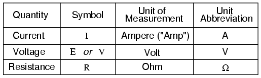
The “symbol” given for each quantity is the standard alphabetical letter used to represent that quantity in an algebraic equation. Standardized letters like these are common in the disciplines of physics and engineering and are internationally recognized. The “unit abbreviation” for each quantity represents the alphabetical symbol used as a shorthand notation for its particular unit of measurement. And, yes, that strange-looking “horseshoe” symbol is the capital Greek letter Ω, just a character in a foreign alphabet (apologies to any Greek readers here).

Each unit of measurement is named after a famous experimenter in electricity: The amp after the Frenchman Andre M. Ampere, the volt after the Italian Alessandro Volta, and the ohm after the German Georg Simon Ohm.
The mathematical symbol for each quantity is meaningful as well. The “R” for resistance and the “V” for voltage are both self-explanatory, whereas “I” for current seems a bit weird. The “I” is thought to have been meant to represent “Intensity” (of charge flow), and the other symbol for voltage, “E,” stands for “Electromotive force.” From what research I’ve been able to do, there seems to be some dispute over the meaning of “I.” The symbols “E” and “V” are interchangeable for the most part, although some texts reserve “E” to represent voltage across a source (such as a battery or generator) and “V” to represent voltage across anything else.
All of these symbols are expressed using capital letters, except in cases where a quantity (especially voltage or current) is described in terms of a brief period of time (called an “instantaneous” value). For example, the voltage of a battery, which is stable over a long period of time, will be symbolized with a capital letter “E,” while the voltage peak of a lightning strike at the very instant it hits a power line would most likely be symbolized with a lower-case letter “e” (or lower-case “v”) to designate that value as being at a single moment in time. This same lower-case convention holds true for current as well, the lower-case letter “i” representing current at some instant in time. Most direct-current (DC) measurements, however, being stable over time, will be symbolized with capital letters.

Coulomb and Electric Charge

One foundational unit of electrical measurement often taught in the beginnings of electronics courses but used infrequently afterward, is the unit of the coulomb, which is a measure of electric charge proportional to the number of electrons in an imbalanced state. One coulomb of charge is equal to 6,250,000,000,000,000,000 electrons. The symbol for electric charge quantity is the capital letter “Q,” with the unit of coulombs abbreviated by the capital letter “C.” It so happens that the unit for current flow, the amp, is equal to 1 coulomb of charge passing by a given point in a circuit in 1 second of time. Cast in these terms, current is the rate of electric charge motion through a conductor.
As stated before, voltage is the measure of potential energy per unit chargeavailable to motivate current flow from one point to another. Before we can precisely define what a “volt” is, we must understand how to measure this quantity we call “potential energy.” The general metric unit for energy of any kind is the joule, equal to the amount of work performed by a force of 1 newton exerted through a motion of 1 meter (in the same direction). In British units, this is slightly less than 3/4 pound of force exerted over a distance of 1 foot. Put in common terms, it takes about 1 joule of energy to lift a 3/4 pound weight 1 foot off the ground, or to drag something a distance of 1 foot using a parallel pulling force of 3/4 pound. Defined in these scientific terms, 1 volt is equal to 1 joule of electric potential energy per (divided by) 1 coulomb of charge. Thus, a 9-volt battery releases 9 joules of energy for every coulomb of charge moved through a circuit.
These units and symbols for electrical quantities will become very important to know as we begin to explore the relationships between them in circuits.

The Ohm’s Law Equation

Ohm’s principal discovery was that the amount of electric current through a metal conductor in a circuit is directly proportional to the voltage impressed across it, for any given temperature. Ohm expressed his discovery in the form of a simple equation, describing how voltage, current, and resistance interrelate:


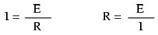
In this algebraic expression, voltage (E) is equal to current (I) multiplied by resistance (R). Using algebra techniques, we can manipulate this equation into two variations, solving for I and for R, respectively:


Analyzing Simple Circuits with Ohm’s Law

Let’s see how these equations might work to help us analyze simple circuits:


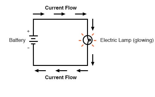
In the above circuit, there is only one source of voltage (the battery, on the left) and only one source of resistance to current (the lamp, on the right). This makes it very easy to apply Ohm’s Law. If we know the values of any two of the three quantities (voltage, current, and resistance) in this circuit, we can use Ohm’s Law to determine the third.

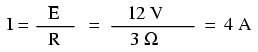
In this first example, we will calculate the amount of current (I) in a circuit, given values of voltage (E) and resistance (R):


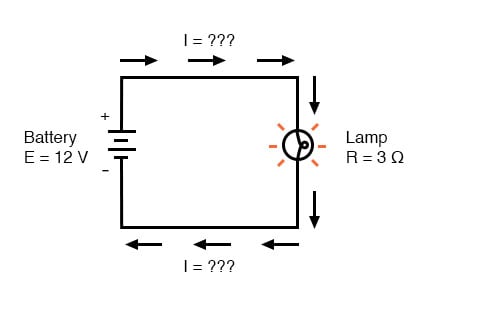
What is the amount of current (I) in this circuit?


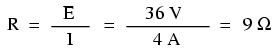
In this second example, we will calculate the amount of resistance (R) in a circuit, given values of voltage (E) and current (I):


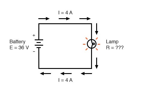
What is the amount of resistance (R) offered by the lamp?


In the last example, we will calculate the amount of voltage supplied by a battery, given values of current (I) and resistance (R):


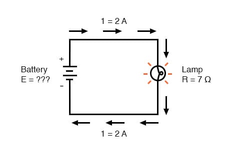
What is the amount of voltage provided by the battery?


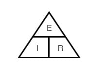
Ohm’s Law Triangle Technique

Ohm’s Law is a very simple and useful tool for analyzing electric circuits. It is used so often in the study of electricity and electronics that it needs to be committed to memory by the serious student. For those who are not yet comfortable with algebra, there’s a trick to remembering how to solve for anyone quantity, given the other two. First, arrange the letters E, I, and R in a triangle like this:


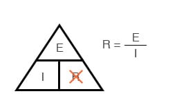
If you know E and I, and wish to determine R, just eliminate R from the picture and see what’s left:


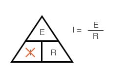
If you know E and R, and wish to determine I, eliminate I and see what’s left:


Lastly, if you know I and R, and wish to determine E, eliminate E and see what’s left:


Eventually, you’ll have to be familiar with algebra to seriously study electricity and electronics, but this tip can make your first calculations a little easier to remember. If you are comfortable with algebra, all you need to do is commit E=IR to memory and derive the other two formulae from that when you need them!

Review
  • • Voltage measured in volts, symbolized by the letters “E” or “V”.
  • • Current measured in amps, symbolized by the letter “I”.
  • • Resistance measured in ohms, symbolized by the letter “R”.
  • • Ohm’s Law: E = IR ; I = E/R ; R = E/I
Share:

LESSON IN ELECTRIC CIRCUT

Lessons in Electric Circuits


Image result for electrical engineering BOOKS
This free electrical engineering textbook provides a series of volumes covering electricity and electronics. The information provided is great for students, makers, and professionals who are looking to refresh or expand their knowledge in this field. These textbooks were written by Tony R. Kuphaldt and released under the Design Science License.

YOU ARE ALSO READ ALL LEESON FROM UNDER THESE GIVEN BELOW; 

It was discovered centuries ago that certain types of materials would mysteriously attract one another after being rubbed together. For example, after rubbing a piece of silk against a piece of glass, the silk and glass would tend to stick together. Indeed, there was an attractive force that could be demonstrated even when the two materials were separated:
Glass and silk aren’t the only materials known to behave like this. Anyone who has ever brushed up against a latex balloon only to find that it tries to stick to them has experienced this same phenomenon. Paraffin wax and wool cloth are another pair of materials early experimenters recognized as manifesting attractive forces after being rubbed together:
This phenomenon became even more interesting when it was discovered that identical materials, after having been rubbed with their respective cloths, always repelled each other:
It was also noted that when a piece of glass rubbed with silk was exposed to a piece of wax rubbed with wool, the two materials would attract one another:
Furthermore, it was found that any material demonstrating properties of attraction or repulsion after being rubbed could be classed into one of two distinct categories: attracted to glass and repelled by wax, or repelled by glass and attracted to wax. It was either one or the other: there were no materials found that would be attracted to or repelled by both glass and wax, or that reacted to one without reacting to the other.
More attention was directed toward the pieces of cloth used to do the rubbing. It was discovered that after rubbing two pieces of glass with two pieces of silk cloth, not only did the glass pieces repel each other but so did the cloths. The same phenomenon held for the pieces of wool used to rub the wax:
Now, this was really strange to witness. After all, none of these objects were visibly altered by the rubbing, yet they definitely behaved differently than before they were rubbed. Whatever change took place to make these materials attract or repel one another was invisible.
Some experimenters speculated that invisible “fluids” were being transferred from one object to another during the process of rubbing and that these “fluids” were able to effect a physical force over a distance. Charles Dufay was one of the early experimenters who demonstrated that there were definitely two different types of changes wrought by rubbing certain pairs of objects together. The fact that there was more than one type of change manifested in these materials was evident by the fact that there were two types of forces produced: attraction and repulsion. The hypothetical fluid transfer became known as a charge.
One pioneering researcher, Benjamin Franklin, came to the conclusion that there was only one fluid exchanged between rubbed objects, and that the two different “charges” were nothing more than either an excess or a deficiency of that one fluid. After experimenting with wax and wool, Franklin suggested that the coarse wool removed some of this invisible fluid from the smooth wax, causing an excess of fluid on the wool and a deficiency of fluid on the wax. The resulting disparity in fluid content between the wool and wax would then cause an attractive force, as the fluid tried to regain its former balance between the two materials.
Postulating the existence of a single “fluid” that was either gained or lost through rubbing accounted best for the observed behavior: that all these materials fell neatly into one of two categories when rubbed, and most importantly, that the two active materials rubbed against each other always fell into opposing categories as evidenced by their invariable attraction to one another. In other words, there was never a time where two materials rubbed against each other both became either positive or negative.
Following Franklin’s speculation of the wool rubbing something off of the wax, the type of charge that was associated with rubbed wax became known as “negative” (because it was supposed to have a deficiency of fluid) while the type of charge associated with the rubbing wool became known as “positive” (because it was supposed to have an excess of fluid). Little did he know that his innocent conjecture would cause much confusion for students of electricity in the future!
Precise measurements of electrical charge were carried out by the French physicist Charles Coulomb in the 1780s using a device called a torsional balance measuring the force generated between two electrically charged objects. The results of Coulomb’s work led to the development of a unit of electrical charge named in his honor, the coulomb. If two “point” objects (hypothetical objects having no appreciable surface area) were equally charged to a measure of 1 coulomb, and placed 1 meter (approximately 1 yard) apart, they would generate a force of about 9 billion newtons (approximately 2 billion pounds), either attracting or repelling depending on the types of charges involved. The operational definition of a coulomb as the unit of electrical charge (in terms of force generated between point charges) was found to be equal to an excess or deficiency of about 6,250,000,000,000,000,000 electrons. Or, stated in reverse terms, one electron has a charge of about 0.00000000000000000016 coulombs. Being that one electron is the smallest known carrier of electric charge, this last figure of charge for the electron is defined as the elementary charge.
It was discovered much later that this “fluid” was actually composed of extremely small bits of matter called electrons, so named in honor of the ancient Greek word for amber: another material exhibiting charged properties when rubbed with cloth.

The Composition of the Atom

Experimentation has since revealed that all objects are composed of extremely small “building-blocks” known as atoms and that these atoms are in turn composed of smaller components known as particles. The three fundamental particles comprising most atoms are called protonsneutronsand electrons. Whilst the majority of atoms have a combination of protons, neutrons, and electrons, not all atoms have neutrons; an example is the protium isotope (1H1) of hydrogen (Hydrogen-1) which is the lightest and most common form of hydrogen which only has one proton and one electron. Atoms are far too small to be seen, but if we could look at one, it might appear something like this:
Even though each atom in a piece of material tends to hold together as a unit, there’s actually a lot of empty space between the electrons and the cluster of protons and neutrons residing in the middle.
This crude model is that of the element carbon, with six protons, six neutrons, and six electrons. In any atom, the protons and neutrons are very tightly bound together, which is an important quality. The tightly-bound clump of protons and neutrons in the center of the atom is called the nucleus, and the number of protons in an atom’s nucleus determines its elemental identity: change the number of protons in an atom’s nucleus, and you change the type of atom that it is. In fact, if you could remove three protons from the nucleus of an atom of lead, you will have achieved the old alchemists’ dream of producing an atom of gold! The tight binding of protons in the nucleus is responsible for the stable identity of chemical elements, and the failure of alchemists to achieve their dream.
Neutrons are much less influential on the chemical character and identity of an atom than protons, although they are just as hard to add to or remove from the nucleus, being so tightly bound. If neutrons are added or gained, the atom will still retain the same chemical identity, but its mass will change slightly and it may acquire strange nuclear properties such as radioactivity.
However, electrons have significantly more freedom to move around in an atom than either protons or neutrons. In fact, they can be knocked out of their respective positions (even leaving the atom entirely!) by far less energy than what it takes to dislodge particles in the nucleus. If this happens, the atom still retains its chemical identity, but an important imbalance occurs. Electrons and protons are unique in the fact that they are attracted to one another over a distance. It is this attraction over distance which causes the attraction between rubbed objects, where electrons are moved away from their original atoms to reside around atoms of another object.
Electrons tend to repel other electrons over a distance, as do protons with other protons. The only reason protons bind together in the nucleus of an atom is because of a much stronger force called the strong nuclear forcewhich has effect only under very short distances. Because of this attraction/repulsion behavior between individual particles, electrons and protons are said to have opposite electric charges. That is, each electron has a negative charge, and each proton a positive charge. In equal numbers within an atom, they counteract each other’s presence so that the net charge within the atom is zero. This is why the picture of a carbon atom has six electrons: to balance out the electric charge of the six protons in the nucleus. If electrons leave or extra electrons arrive, the atom’s net electric charge will be imbalanced, leaving the atom “charged” as a whole, causing it to interact with charged particles and other charged atoms nearby. Neutrons are neither attracted to or repelled by electrons, protons, or even other neutrons and are consequently categorized as having no charge at all.
The process of electrons arriving or leaving is exactly what happens when certain combinations of materials are rubbed together: electrons from the atoms of one material are forced by the rubbing to leave their respective atoms and transfer over to the atoms of the other material. In other words, electrons comprise the “fluid” hypothesized by Benjamin Franklin.

What is Static Electricity?

The result of an imbalance of this “fluid” (electrons) between objects is called static electricity. It is called “static” because the displaced electrons tend to remain stationary after being moved from one insulating material to another. In the case of wax and wool, it was determined through further experimentation that electrons in the wool actually transferred to the atoms in the wax, which is exactly opposite of Franklin’s conjecture! In honor of Franklin’s designation of the wax’s charge being “negative” and the wool’s charge being “positive,” electrons are said to have a “negative” charging influence. Thus, an object whose atoms have received a surplus of electrons is said to be negatively charged, while an object whose atoms are lacking electrons is said to be positively charged, as confusing as these designations may seem. By the time the true nature of electric “fluid” was discovered, Franklin’s nomenclature of electric charge was too well established to be easily changed, and so it remains to this day.
Michael Faraday proved (1832) that static electricity was the same as that produced by a battery or a generator. Static electricity is, for the most part, a nuisance. Black powder and smokeless powder have graphite added to prevent ignition due to static electricity. It causes damage to sensitive semiconductor circuitry. While it is possible to produce motors powered by high voltage and low current characteristic of static electricity, this is not economic. The few practical applications of static electricity include xerographic printing, the electrostatic air filter, and the high voltage Van de Graaff generator.

REVIEW:
  • • All materials are made up of tiny “building blocks” known as atoms.
  • • All naturally occurring atoms contain particles called electronsprotons, and neutrons, with the exception of the protium isotope (1H1) of hydrogen.
  • • Electrons have a negative (-) electric charge.
  • • Protons have a positive (+) electric charge.
  • • Neutrons have no electric charge.
  • • Electrons can be dislodged from atoms much easier than protons or neutrons.
  • • The number of protons in an atom’s nucleus determines its identity as a unique element.
Share:

Tuesday 9 April 2019

INTEGRETED CIRCUT

INTEGRETED CICUT
An integrated circuit or monolithic integrated circuit (also referred to as an IC, a chip, or a microchip) is a set of electronic circuits on one small flat piece (or "chip") of semiconductor material that is normally silicon. The integration of large numbers of tiny transistors into a small chip results in circuits that are orders of magnitude smaller, cheaper, and faster than those constructed of discrete electronic components. The IC's mass production capability, reliability and building-block approach to circuit design has ensured the rapid adoption of standardized ICs in place of designs using discrete transistors. ICs are now used in virtually all electronic equipment and have revolutionized the world of electronicsComputersmobile phones, and other digital home appliances are now inextricable parts of the structure of modern societies, made possible by the small size and low cost of ICs.

Integrated circuits were made practical by mid-20th-century technology advancements in semiconductor device fabrication. Since their origins in the 1960s, the size, speed, and capacity of chips have progressed enormously, driven by technical advances that fit more and more transistors on chips of the same size – a modern chip may have many billions of transistors in an area the size of a human fingernail. These advances, roughly following Moore's law, make computer chips of today possess millions of times the capacity and thousands of times the speed of the computer chips of the early 1970s.
INVENTION

ICs have two main advantages over discrete circuits: cost and performance. Cost is low because the chips, with all their components, are printed as a unit by photolithography rather than being constructed one transistor at a time. Furthermore, packaged ICs use much less material than discrete circuits. Performance is high because the IC's components switch quickly and consume comparatively little power because of their small size and close proximity. The main disadvantage of ICs is the high cost to design them and fabricate the required photomasks. This high initial cost means ICs are only practical when high production volumes are anticipated.
Early developments of the integrated circuit go back to 1949, when German engineer(Siemens AG) filed a patent for an integrated-circuit-like semiconductor amplifying device showing five transistors on a common substrate in a 3-stage amplifier arrangement. Jacobi disclosed small and cheap hearing aids as typical industrial applications of his patent. An immediate commercial use of his patent has not been reported.
The idea of the integrated circuit was conceived by Geoffrey Dummer (1909–2002), a radar scientist working for the Royal Radar Establishment of the British Ministry of Defence. Dummer presented the idea to the public at the Symposium on Progress in Quality Electronic Components in Washington, D.C. on 7 May 1952.[7] He gave many symposia publicly to propagate his ideas and unsuccessfully attempted to build such a circuit in 1956.
A precursor idea to the IC was to create small ceramic squares (wafers), each containing a single miniaturized component. Components could then be integrated and wired into a bidimensional or tridimensional compact grid. This idea, which seemed very promising in 1957, was proposed to the US Army by Jack Kilby and led to the short-lived Micromodule Program (similar to 1951's Project Tinkertoy). However, as the project was gaining momentum, Kilby came up with a new, revolutionary design: the IC.
Jack Kilby's original integrated circuit
Newly employed by Texas Instruments, Kilby recorded his initial ideas concerning the integrated circuit in July 1958, successfully demonstrating the first working integrated example on 12 September 1958. In his patent application of 6 February 1959,]Kilby described his new device as "a body of semiconductor material … wherein all the components of the electronic circuit are completely integrated." The first customer for the new invention was the US Air Force.
Kilby won the 2000 Nobel Prize in Physics for his part in the invention of the integrated circuit.His work was named an IEEE Milestone in 2009.
Half a year after Kilby, Robert Noyce at Fairchild Semiconductor developed a new variety of integrated circuit, more practical than Kilby's implementation. Noyce's design was made of silicon, whereas Kilby's chip was made of germanium. Noyce credited Kurt Lehovec of Sprague Electricfor the principle of p–n junction isolation, a key concept behind the IC. This isolation allows each transistor to operate independently despite being part of the same piece of silicon.
TERMINOLOGY
A circuit in which all or some of the circuit elements are inseparably associated and electrically interconnected so that it is considered to be indivisible for the purposes of construction and commerce.
Circuits meeting this definition can be constructed using many different technologies, including thin-film transistorsthick-film technologies, or hybrid integrated circuits. However, in general usage integrated circuit has come to refer to the single-piece circuit construction originally known as a monolithic integrated circuit.
Arguably, the first examples of integrated circuits would include the Loewe 3NF.[4] Although far from a monolithic construction, it certainly meets the definition given above.

Share:

HOW TO WASTE CONVERT INTO ENERGY

HOW TO WASTE CONVERT INTO ENERGY:


Waste-to-energy (WtE) or energy-from-waste (EfW) is the process of generating energy in the form of electricity and/or heat from the primary treatment of waste, or the processing of waste into a fuel source. WtE is a form of energy recovery. Most WtE processes generate electricity and/or heat directly through combustion, or produce a combustible fuel commodity, such as methanemethanolethanol or synthetic fuels.

HISTORY:
The first incinerator or "Destructor" was built in Nottingham UK in 1874 by Manlove, Alliott & Co. Ltd. to the design of Alfred Fryer.
The first US incinerator was built in 1885 on Governors Island in New York, New York.
The first waste incinerator in Denmark was built in 1903 in Frederiksberg.
The first facility in the Czech Republic was built in 1905 in Brno.
Gasification and pyrolysis processes have been known and used for centuries and for coal as early as the 18th century.... Development technologies for processing [residual solid mixed waste] has only become a focus of attention in recent years stimulated by the search for more efficient energy recovery. (2004) 

MethodsEdit

IncinerationEdit

Incineration, the combustion of organic material such as waste with energy recovery, is the most common WtE implementation. All new WtE plants in OECD countries incinerating waste (residual MSW, commercial, industrial or RDF) must meet strict emission standards, including those on nitrogen oxides (NOx), sulphur dioxide (SO2), heavy metals and dioxins. Hence, modern incineration plants are vastly different from old types, some of which neither recovered energy nor materials. Modern incinerators reduce the volume of the original waste by 95-96 percent, depending upon composition and degree of recovery of materials such as metals from the ash for recycling.
Incinerators may emit fine particulate, heavy metals, trace dioxin and acid gas, even though these emissions are relatively low from modern incinerators. Other concerns include proper management of residues: toxic fly ash, which must be handled in hazardous waste disposal installation as well as incinerator bottom ash (IBA), which must be reused properly.
Critics argue that incinerators destroy valuable resources and they may reduce incentives for recycling.[10] The question, however, is an open one, as European countries which recycle the most (up to 70%) also incinerate to avoid landfilling.
Incinerators have electric efficiencies of 14-28%.In order to avoid losing the rest of the energy, it can be used for e.g. district heating (cogeneration). The total efficiencies of cogeneration incinerators are typically higher than 80% (based on the lower heating value of the waste).
The method of incineration to convert municipal solid waste (MSW) is a relatively old method of WtE generation. Incineration generally entails burning waste (residual MSW, commercial, industrial and RDF) to boil water which powers steam generatorsthat generate electric energy and heat to be used in homes, businesses, institutions and industries. One problem associated is the potential for pollutants to enter the atmosphere with the flue gases from the boiler. These pollutants can be acidic and in the 1980s were reported to cause environmental degradation by turning rain into acid rain. Since then, the industry has removed this problem by the use of lime scrubbers and electro-static precipitators on smokestacks. By passing the smoke through the basic lime scrubbers, any acids that might be in the smoke are neutralized which prevents the acid from reaching the atmosphere and hurting the environment. Many other devices, such as fabric filters, reactors, and catalysts destroy or capture other regulated pollutants. According to the New York Times, modern incineration plants are so clean that "many times more dioxin is now released from home fireplaces and backyard barbecues than from incineration.  According to the German Environmental Ministry, "because of stringent regulations, waste incineration plants are no longer significant in terms of emissions of dioxins, dust, and heavy metals",

OtherEdit

There are a number of other new and emerging technologies that are able to produce energy from waste and other fuels without direct combustion. Many of these technologies have the potential to produce more electric power from the same amount of fuel than would be possible by direct combustion. This is mainly due to the separation of corrosive components (ash) from the converted fuel, thereby allowing higher combustion temperatures in e.g. boilersgas turbinesinternal combustion enginesfuel cells. Some are able to efficiently convert the energy into liquid or gaseous fuels:
Pyrolysis Plant
Landfill Gas Collection
Non-thermal technologies:

Global developmentsEdit

During the 2001–2007 period, the waste-to-energy capacity increased by about four million metric tons per year. Japan and China each built several plants based on direct smelting or on fluidized bed combustion of solid waste. In China there are about 434 waste-to-energy plants in early 2016. Japan is the largest user in thermal treatment of municipal solid waste in the world, with 40 million tons. Some of the newest plants use stoker technology and others use the advanced oxygen enrichment technology. Several treatment plants exist worldwide using relatively novel processes such as direct smelting, the Ebara fluidization process and the Thermoselect JFE gasification and melting technology process.In India its first energy bio-science center was developed to reduce the country’s green house gases and its dependency on fossil fuel.As of June 2014, Indonesia had a total of 93.5 MW installed capacity of waste-to-energy, with a pipeline of projects in different preparation phases together amounting to another 373MW of capacity.
Biofuel Energy Corporation of Denver, CO, opened two new biofuel plants in Wood River, Nebraska, and Fairmont, Minnesota, in July 2008. These plants use distillation to make ethanol for use in motor vehicles and other engines. Both plants are currently reported to be working at over 90% capacity. Fulcrum BioEnergy incorporated located in Pleasanton, California, is building a WtE plant near Reno, NV. The plant is scheduled to open in 2019 under the name of Sierra BioFuels plant. BioEnergy incorporated predicts that the plant will produce approximately 10.5 million gallons per year of ethanol from nearly 200,000 tons per year of MSW.
Waste to energy technology includes fermentation, which can take biomass and create ethanol, using waste cellulosic or organic material. In the fermentation process, the sugar in the waste is changed to carbon dioxide and alcohol, in the same general process that is used to make wine. Normally fermentation occurs with no air present. Esterification can also be done using waste to energy technologies, and the result of this process is biodiesel. The cost effectiveness of esterification will depend on the feedstock being used, and all the other relevant factors such as transportation distance, amount of oil present in the feedstock, and others. Gasification and pyrolysis by now can reach gross thermal conversion efficiencies (fuel to gas) up to 75%, however a complete combustion is superior in terms of fuel conversion efficiency.[Some pyrolysis processes need an outside heat source which may be supplied by the gasification process, making the combined process self-sustaining.

Carbon dioxide emissionsEdit

In thermal WtE technologies, nearly all of the carbon content in the waste is emitted as carbon dioxide (CO
2
) to the atmosphere (when including final combustion of the products from pyrolysis and gasification; except when producing bio-char for fertilizer). Municipal solid waste (MSW) contain approximately the same mass fraction of carbon as CO
2
 itself (27%), so treatment of 1 metric ton (1.1 short tons) of MSW produce approximately 1 metric ton (1.1 short tons) of CO
2
.
In the event that the waste was landfilled, 1 metric ton (1.1 short tons) of MSW would produce approximately 62 cubic metres (2,200 cu ft) methane via the anaerobic decomposition of the biodegradable part of the waste. This amount of methane has more than twice the global warming potential than the 1 metric ton (1.1 short tons) of CO
2
, which would have been produced by combustion. In some countries, large amounts of landfill gas are collected, but still the global warming potential of the landfill gas emitted to atmosphere in e.g. the US in 1999 was approximately 32% higher than the amount of CO
2
 that would have been emitted by combustion.
In addition, nearly all biodegradable waste is biomass. That is, it has biological origin. This material has been formed by plants using atmospheric CO
2
 typically within the last growing season. If these plants are regrown the CO
2
 emitted from their combustion will be taken out from the atmosphere once more.
Such considerations are the main reason why several countries administrate WtE of the biomass part of waste as renewable energy. The rest—mainly plastics and other oil and gas derived products—is generally treated as non-renewables.

Determination of the biomass fractionEdit

MSW to a large extent is of biological origin (biogenic), e.g. paper, cardboard, wood, cloth, food scraps. Typically half of the energy content in MSW is from biogenic material.Consequently, this energy is often recognised as renewable energy according to the waste input.
Several methods have been developed by the European CEN 343 working group to determine the biomass fraction of waste fuels, such as Refuse Derived Fuel/Solid Recovered Fuel. The initial two methods developed (CEN/TS 15440) were the manual sorting method and the selective dissolution method. A detailed systematic comparison of these two methods was published in 2010. Since each method suffered from limitations in properly characterizing the biomass fraction, two alternative methods have been developed.
The first method uses the principles of radiocarbon dating. A technical review (CEN/TR 15591:2007) outlining the carbon 14 method was published in 2007. A technical standard of the carbon dating method (CEN/TS 15747:2008) will be published in 2008. In the United States, there is already an equivalent carbon 14 method under the standard method ASTM D6866.
The second method (so-called balance method) employs existing data on materials composition and operating conditions of the WtE plant and calculates the most probable result based on a mathematical-statistical model. Currently the balance method is installed at three Austrian and eight Danish incinerators.
A comparison between both methods carried out at three full-scale incinerators in Switzerland showed that both methods came to the same results.
Carbon 14 dating can determine with precision the biomass fraction of waste, and also determine the biomass calorific value. Determining the calorific value is important for green certificate programs such as the Renewable Obligation Certificate program in the United Kingdom. These programs award certificates based on the energy produced from biomass. Several research papers, including the one commissioned by the Renewable Energy Association in the UK, have been published that demonstrate how the carbon 14 result can be used to calculate the biomass calorific value. The UK gas and electricity markets authority, Ofgem, released a statement in 2011 accepting the use of Carbon 14 as a way to determine the biomass energy content of waste feedstock under their administration of the Renewables Obligation. Their Fuel Measurement and Sampling (FMS) questionnaire describes the information they look for when considering such proposals.

Examples of waste-to-energy plantsEdit


According to the International Solid Waste Association (ISWA) there are 431 WtE plants in Europe (2005) and 89 in the United States (2004).The following are some examples of WtE plants.
Waste incineration WtE plants
Liquid fuel producing plants
A single plant is currently under construction. None are yet in commercial operation:
  • Edmonton Waste-to-ethanol Facility located in Edmonton, Alberta, Canada based on the Enerkem-process, fueled by RDF. Initially scheduled for completion during 2010commissioning of front-end systems commenced in December 2013 and Enerkem then expected initial methanol production during 2014.Production start has been delayed several times. As of spring 2016 Enerkem expected ethanol production to commence some time ín 2017, and no public confirmation of any actual RDF processing was available.
Plasma Gasification Waste-to-Energy plants
  • The US Air Force once tested a Transportable Plasma Waste to Energy System (TPWES) facility (PyroGenesis technology) at Hurlburt Field, Florida. The plant, which cost $7.4 million to construct, was closed and sold at a government liquidation auction in May 2013, less than three years after its commissioning. The opening bid was $25. The winning bid was sealed.
Besides large plants, domestic waste-to-energy incinerators also exist. For example, the refuge de Sarenne has a domestic waste-to-energy plant. It is made by combining a wood-fired gasification boiler with a Stirling motor.
Share:

Ohm's Law

Ohm's Law The first, and perhaps most important, the relationship between current, voltage, and resistance is called Ohm’s Law, disc...

Search This Blog

Blog Archive

Powered by Blogger.